custom shafts
Custom Shafts & Axles — Turned & Ground to Tolerance
We manufacture custom shafts to your drawing — turned, milled and finished in one factory, with a material certificate and pre-shipment photos before the goods ship.
Upload your drawing (STEP, IGES, DWG, DXF, PDF) — we return DFM feedback and a quote within 24 hours.
- Tolerance
- ±0.01 mm
- MOQ
- From 50 pcs
- Sample
- 5–10 days
- Production
- 25–35 days
- Documents
- MTR + pre-shipment photos
What this part is and where it is used
A shaft is a rotating bar or axle that carries gears, pulleys, sprockets, couplings or wheels and transmits torque along its length. We turn custom shafts and axles from bar stock to the customer’s drawing, producing the diameters, shoulders, bearing seats, grooves, keyways, splines and threaded ends in one turning programme. The part is defined by its overall length, the sequence of diameters along it, and the tolerance on each seat and shoulder, so straightness and concentricity between sections matter as much as any single dimension.
Buyers specify these for gearboxes, motors, pumps, conveyors, fans, agricultural machinery and general rotating equipment. A typical drawing mixes tight bearing seats with looser mid-sections, plus a keyway or spline at one end and a thread at the other. We plan each shaft so the critical seats are finished in the same set-up that controls their run to the centre axis.
Types and variants we manufacture
Stepped shafts are the most common request: a single bar with several diameters, each with its own tolerance and a shoulder or radius between them. Splined shafts carry a torque-coupling spline, involute or straight-sided, at one or both ends, and are turned then milled to suit the mating hub. Keyed shafts include one or more keyways for a pulley or gear, cut after turning so the keyway sits true to the axis. Threaded ends — external threads for nuts, or drilled and tapped centres — are turned or thread-milled per the drawing.
We also machine axles, pinion shafts and worm shafts, where a gear or worm profile is cut onto the same bar as the bearing journals. Common detail features include circlip grooves, O-ring grooves, undercuts, chamfers and centre holes. Where a shaft needs a hardened journal or a ground seat, heat treatment and grinding are arranged in-house or through our vetted partner network, and every feature is produced from the same drawing so the ends and seats stay concentric.
Materials, threads and finishes
Material follows load and duty. Carbon steel 1045 and free-cutting 1215 suit general shafts and axles, while alloy steel 4140 gives higher strength and responds well to induction hardening for journals. Stainless steel 303, 304, 304L, 316, 316L and 17-4PH cover washdown, food, marine and high-strength duties, and aluminium 2024, 6061 or 7075 suits light, low-inertia shafts. Brass, copper, bronze and titanium are available where conductivity or weight drives the choice. See the materials page for the full working list.
Threads are cut to metric or inch standards, external on the ends or internal in tapped centres and cross-holes. Finishes and treatment are ordered to suit the application: induction hardening for seats, and anodising, zinc or nickel plating or black oxide through our vetted partner network, managed under one quality process. Each shaft ships with a material certificate (MTR) documenting the bar stock.
Industries and applications
Shafts and axles are the backbone of rotating equipment, so the same drawing discipline applies across industries. Gearbox and power-transmission builders order parallel shafts and pinion shafts, often paired with the gears on our custom gears page. Pump, fan and compressor makers specify stepped shafts with tight bearing seats, while conveyor and material-handling equipment use keyed shafts for rollers and drives.
Agricultural and construction machinery call for longer, higher-strength shafts, frequently from 4140 with hardened journals. Food-processing and packaging equipment prefer stainless shafts for washdown, and automation and robotics use small, light aluminium or stainless shafts for actuators and stages. Because we work from your drawing rather than a catalogue, a replacement shaft and a full production lot follow the same route — only the quantity changes.
Why order this part from our factory
Shafts need every diameter on one axis, so they are a natural fit for a factory that turns and mills in one place. We produce the full part — diameters, shoulders, threads, keyways and splines — in our factory in Qidong City, Jiangsu Province, China, without farming the critical seats out between shops. Heat treatment and grinding are available in-house or through our vetted partner network, so a hardened journal is not a reason to split the order.
We hold ±0.01 mm on precision features and ISO 2768-m as the general tolerance, with attention to straightness and concentricity between bearing seats. MOQ is from 50 pieces with samples from 1 piece in 5–10 days; production runs 25–35 days after sample approval. Quotes come back within 24 hours with DFM feedback on stock size, centre holes and feature order. Each shipment leaves with a material certificate (MTR) and pre-shipment photos. Start with our request-a-quote form, or review tolerances before you send the drawing.
Turning, mill-turn and Swiss: which route the part needs
Three different machine configurations are called turning, and the part decides which one is right.
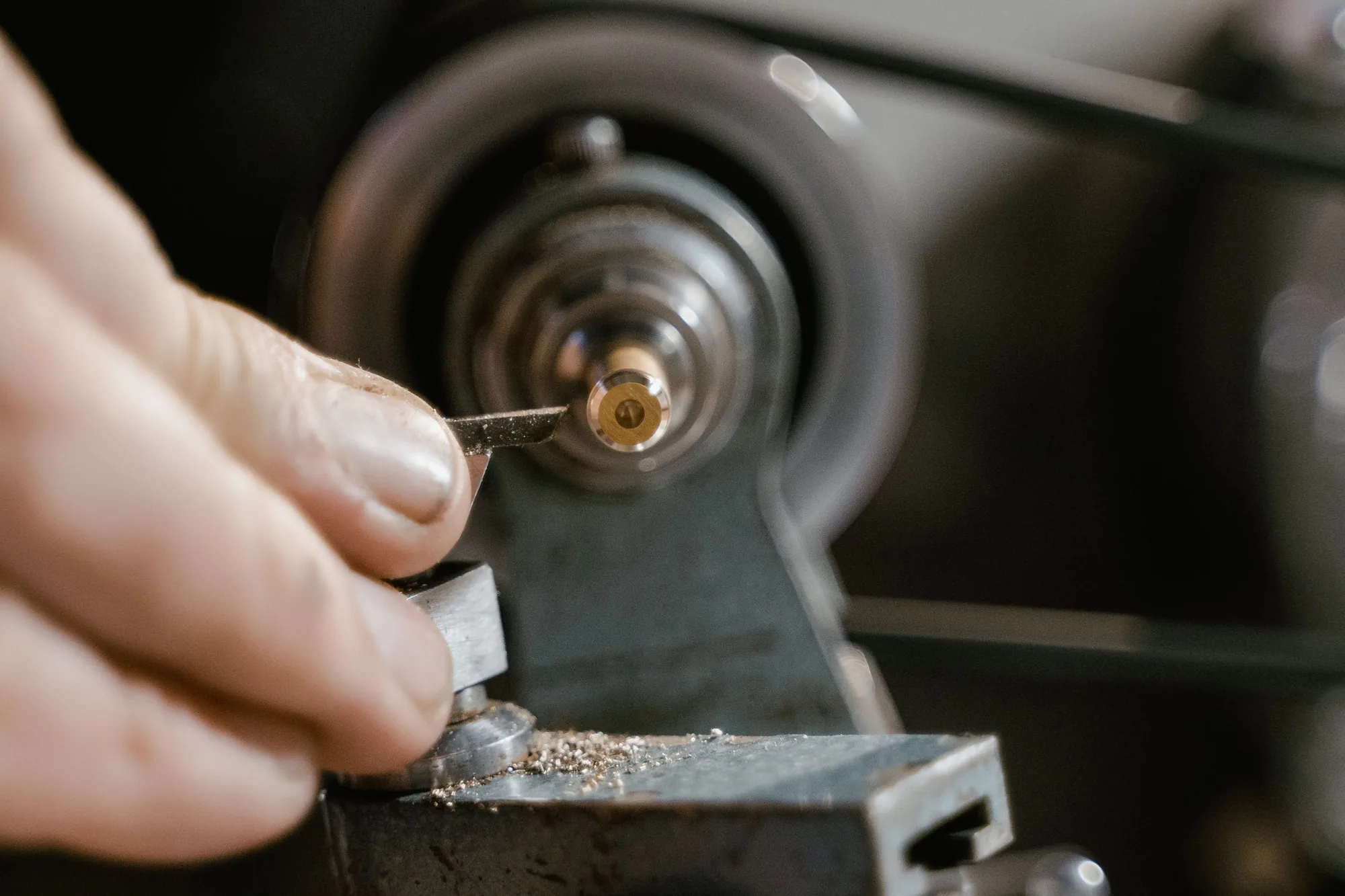
Standard CNC turning holds the workpiece in a chuck or feeds it from a bar, and the tool moves against a rotating part. It is the default for parts whose length is up to about three times their diameter, and it handles the widest range of sizes.
Swiss-type turning slides the bar through a guide bushing and cuts right at the bushing, so the material is supported within a millimetre or two of the cutting edge. That support is the whole point: a part with a length-to-diameter ratio of 8:1 or 10:1 that would deflect and taper on a standard lathe holds size on a Swiss machine. It suits small diameters — typically up to about 32 mm — produced in volume.
Mill-turn adds live tooling to the turret, so flats, slots, keyways and cross-holes are cut in the same cycle as the diameters. A part that would otherwise be turned, then re-fixtured on a mill, keeps its concentricity because it is never released from the spindle.
The right question on a turned part is not “can it be turned” but “which of the three holds the tolerance at the cost the volume allows”. A 6 mm pin, 60 mm long, in 5,000 pieces is a Swiss job. The same pin in 80 pieces is a standard lathe with a support. A turned boss with two milled flats is a mill-turn job at any volume.
What the drawing has to define
A turned part is defined by a set of diameters, the features that locate against them, and the datums those features are measured from. When any of the three is missing, the shop has to guess, and a guess on a round part shows up as runout.
Give every diameter with its tolerance, and say which diameter is the functional one. On a shaft with five diameters, the bearing seat is usually the datum and the rest are positioned from it — but the drawing has to say so, because the shop cannot infer which seat matters.
Define the bore the same way: diameter, depth, and whether it is through or blind. A blind bore needs its depth tolerance and its corner condition; a drilled corner is conical, and a flat-bottomed bore is a milling or boring operation rather than a drilling one.
Name the thread in full — nominal diameter, pitch and class. “M10” is not a thread specification; M10 × 1.5 with a class is. On an inch drawing the same applies to UNC or UNF with its class.
Call out the undercuts, reliefs and corner radii that the thread and the grinding wheel will need. A thread that runs into a shoulder without an undercut cannot be cut to the full depth, and the drawing that omits the undercut gets a call from the shop rather than a part.
Concentricity and runout on a round part
On a turned part, the feature that most often decides whether it works is not any single diameter — it is how well the diameters sit on a common axis.
Runout is the error to control. State it as total indicated runout against a specific datum, for example 0.02 mm TIR on the bearing seat relative to the shaft axis. A number attached to a feature and a datum is inspectable; a note saying “concentric” is not.
Two habits prevent most runout problems. First, name the datum as the feature the part was actually held by, because that is where the concentricity physically comes from. Second, keep runout calls to the features that need them — a bearing seat, a seal surface, a gear mounting — rather than applying one tight figure to every diameter, which adds cost without adding function.
Where two features must be coaxial but cannot both be datums, say which one governs. A drawing that names both as datums leaves the shop to choose, and the chosen one will be whichever is cheaper to hold.
Bar stock, blank choice and what it does to the price
Most turned parts start from bar, and the bar diameter is a cost decision that is made before any cutting happens.
The bar has to be at least as large as the biggest outside diameter on the part. Choosing the nearest standard size above that figure leaves the least material to remove. Choosing a size that is 3 mm larger “to be safe” turns into swarf, additional roughing time and, on a long part, more deflection.
Material utilisation on a turned part typically runs between about 40% and 70%, so the material cost is not the bar weight — it is the bar weight divided by how much of it ends up in the part. On a small pin in stainless or titanium, the material can be the dominant cost, and a half-millimetre of unnecessary bar diameter is real money across a production run.
The blank also sets the workholding. Bar-fed work needs the bar to pass through the spindle bore and to be straight enough to feed reliably; a part that is short and large in diameter is better held in a chuck from a sawn blank. When the part starts as a forging or a headed blank, that pre-form is planned first, because it decides what the turning operation has to remove.
Threads on a turned part
Turning produces threads three ways, and the choice affects both strength and cost.
Single-point threading cuts the thread with a form tool following the helix. It works at any diameter and any pitch, needs no special tooling per size, and is the default for low and medium volume — including odd pitches and non-standard diameters.
Thread milling cuts the thread with a rotating cutter orbiting the bore. It suits large internal threads where a tap would be impractical, and it is available on the mill-turn machines, so an internal thread can be produced in the same cycle as the outside diameters and the cross-holes.
Rolled threads form the thread by displacing material rather than cutting it. The grain flow follows the thread form instead of being cut across it, which makes a rolled thread stronger in fatigue than a cut one of the same size. Rolling needs the blank diameter controlled to a specific figure — the pitch diameter of the finished thread — so it is planned at the bar stage rather than chosen at the machine.
For a part that will see cyclic load, rolling is worth asking about at quotation. For a one-off or a large internal thread, it is not.
Surface finish and what turning achieves
Turning leaves a characteristic finish that is a function of feed rate, tool nose radius and material — and it is usually good enough without a second operation.
A general turned finish sits around Ra 1.6 µm to 3.2 µm, which is the normal result of a finishing pass at a sensible feed. Holding Ra 0.8 µm is achievable on a rigid set-up with a fine feed, at the cost of cycle time. Below that, around Ra 0.4 µm, turning is no longer the process and the surface is ground or lapped instead.
Where the finish is functional — a seal running surface, a bearing seat, a sliding bore — state the Ra value and the feature it applies to. Where it is not, avoid specifying a blanket finish: a tight Ra on a decorative diameter adds cycle time for no benefit.
Machining marks run circumferentially on a turned surface, which matters on a sealing face: a radial seal runs against circumferential marks well, while an O-ring face seal wants a different surface. Naming the sealing method on the drawing lets the shop choose the right finishing pass.
Where turned parts get cheaper
Turning economics are driven by setup against cycle time, and the crossover is easy to see once you know the parts.
Below roughly 50 pieces, setup dominates. Programming, bar loading, first-off inspection and any special tooling are spread over a small number of parts, so the piece price is high and the process choice barely matters.
From a few hundred into the thousands, bar feed takes over. A bar-fed lathe runs with minimal operator attention, the setup is amortised, and the piece price falls steeply. This is the range where a small part becomes genuinely cheap — and where choosing the right bar diameter stops being a detail and starts being the price.
Above tens of thousands, dedicated high-volume processes compete with turning. Cold heading and cold forming produce a near-net shape far faster than cutting it from bar, after which a short turning operation finishes the critical diameters. For a fastener-shaped part in volume, that combination usually beats machining from solid — see our cold heading page for where that line sits.
Where the part sits between two of these bands, ask for both routes quoted. The comparison is usually clear enough to decide, and it is cheaper than discovering the answer after the first production run.
Turned-part drawing mistakes we see
Six errors come back on quotations often enough to list.
A missing datum is first. Without one, runout cannot be specified, inspected or held, and the shop will hold the feature that is easiest to measure rather than the one that matters.
Second is a thread with no pitch or class. “M8 thread” on a drawing means the shop picks a pitch, and if the mating part was designed to a different one, the two do not assemble.
Third is a sharp internal corner on a bore that has to take a shoulder. A turned tool has a nose radius, and the corner it leaves is that radius. A square internal corner is either a milling operation or a relief that has to be designed in.
Fourth is a nominal-only wall thickness. A thin wall on a turned part deflects under clamping and cutting pressure, so give the wall a tolerance and, where it is thin, expect the process plan to include a support or a lighter finishing pass.
Fifth is a surface finish specified everywhere. It adds cycle time on features that do not need it.
Sixth is a part that needs a milled feature but is specified as turned only. Mill-turn exists precisely for that part, and naming the process on the drawing removes a re-fixturing step that would otherwise cost concentricity.
How CNC turned parts are quoted
Quoting a turned part comes down to material, cycle time and setup, and each one is answerable from the drawing.
Material is bar weight divided by utilisation, priced at the grade you named. On stainless and titanium parts this line is often the largest single item, so the difference between a 12 mm and a 14 mm bar is visible in the quote.
Cycle time follows from the number of diameters, the thread length, the tolerance band and the finish. A part with two diameters and a thread is a short cycle; a part with eight diameters, two bores, an internal thread and a runout call-out is a longer one, and the runout call-out in particular may need a second operation to hold.
Setup is where a quote moves most with quantity, which is why the same drawing quoted at 50 pieces and at 5,000 pieces can differ by a factor of several on the piece price.
Send the drawing with the material, the quantity and the features that actually govern, and we return a quote within 24 hours with DFM feedback — including, where it applies, a note that the part would run cheaper on a different bar size, as a rolled thread, or as a headed blank finished by turning. MOQ is from 50 pieces with samples from 1 piece in 5–10 days, and production runs 25–35 days after sample approval.
Specifications
| Shaft types | Stepped shafts, splined shafts, keyed shafts, threaded ends, axles, pinion and worm shafts |
|---|---|
| Features | Bearing seats, shoulders, circlip grooves, undercuts, chamfers, centre holes |
| Ends | Threaded, drilled and tapped, or with keyways and splines |
| Splines | Involute or straight-sided splines to drawing |
| Keyways | Standard or non-standard keyway widths to drawing |
| Precision tolerance | ±0.01 mm |
| Straightness & concentricity | Critical seats turned in one set-up to hold run to the centre axis |
| General tolerance | ISO 2768-m unless stated on the drawing |
| Materials | Aluminium 2024/5052/6061/7075, stainless 301/303/304/304L/316/316L/410/416/17-4PH, carbon steel 1045/1215/12L14, alloy steel 4130/4140, tool steel D2/O1, brass, bronze, copper, titanium |
| Heat treatment | Induction hardening and case hardening through our vetted partner network |
| Finishes | Anodising, zinc or nickel plating, black oxide through our vetted partner network |
| MOQ | From 50 pieces (samples from 1 piece) |
| Sample lead time | 5–10 days |
| Production lead time | 25–35 days after sample approval |
| Documents | Material certificate (MTR) + pre-shipment photos |
| Diameter | 3–120 mm, length up to 900 mm |
| Tolerance | ±0.01 mm diameter, 0.02 mm concentricity |
| Secondary | Grinding, heat treat, hard chrome |
| Lot size | 10–5,000 pcs |
| Process | CNC turning with bar feed and chuck work |
| Mill-turn | Live tooling for flats, slots, keyways and cross-holes in one set-up |
| Threads | Internal and external, metric and inch |
| Monthly capacity | Over 100,000 parts |
| Machine types | Swiss turning, fixed-head CNC lathe |
| Process | Cam-operated automatics and CNC screw machines |
| Feeding | Bar-fed turning of small-diameter round bar |
| Part types | Pins, spacers, standoffs, bushings, connectors, threaded inserts, valve stems, nozzles |
| Threads | Metric, UN, BSP, BSPT, NPT |
| Samples | From 1 piece, delivered in 5–10 days |
| Quoting | Within 24 hours with DFM feedback |
| Monthly capacity | Over 100,000 parts |
| Length-to-diameter | Up to 8:1 from bar stock |
Frequently asked questions
Can you make a single custom shaft as a sample?
Yes. Samples start from 1 piece and ship in 5–10 days, so you can confirm fits before ordering a production lot.
Can you machine a splined shaft?
Yes. We turn the journals and cut involute or straight-sided splines to the drawing, keeping the spline and seats on the same axis.
Can you cut a keyway after turning?
Yes. Keyways are milled after turning in the same job so they sit true to the shaft axis.
Do you machine threaded ends?
Yes. External threads and drilled-and-tapped centres are produced to metric or inch standards per the drawing.
Can you hold tight bearing seats?
Yes. We hold ±0.01 mm on precision features and turn critical seats in one set-up to keep straightness and concentricity.
What materials do you turn shafts from?
Aluminium 2024/5052/6061/7075, stainless steel 301/303/304/304L/316/316L/410/416/17-4PH, carbon steel 1045/1215/12L14, alloy steel 4130/4140, tool steel D2/O1, brass, bronze, copper and titanium.
Can you harden a journal?
Yes. Induction hardening and case hardening are available in-house or through our vetted partner network.
What finishes can you apply to a shaft?
Anodising, zinc or nickel plating and black oxide, arranged through our vetted partner network, managed under one quality process.
What is the MOQ?
From 50 pieces for production, with samples from 1 piece.
How long does production take?
25–35 days after sample approval.
Do you provide a material certificate?
Yes. Each shipment includes a material certificate (MTR) and pre-shipment photos.
How fast do you quote?
Within 24 hours, with DFM feedback on stock size and feature order.
What is CNC turning best at?
Turning excels at round, cylindrical features — outside diameters, bores, shoulders, grooves, threads and chamfers — produced efficiently from bar or a chucked blank.
Do you offer mill-turn or live tooling?
Yes. Live tooling adds flats, slots, keyways and cross-holes in the same set-up, so a round part with a side detail is finished without re-fixturing.
Can you turn internal and external threads?
Yes, to metric or inch standards, single-point or thread-milled.
What materials do you turn?
Aluminium 2024/5052/6061/7075, stainless steel 301/303/304/304L/316/316L/410/416/17-4PH, carbon steel 1045/1215/12L14, alloy steel 4130/4140, tool steel D2/O1, brass, bronze, copper and titanium.
Can you start from a forged or headed blank?
Yes. Forging, heading and stamping pre-forms are available in-house or through our vetted partner network.
When should I choose turning over milling?
When the part is dominated by round features. Turning removes material efficiently and keeps diameters concentric, while milling suits pockets and profiles.
Send your drawing — quote in 24 hours
DFM feedback, material certificates and pre-shipment photos come with every order.