DFM guide
DFM Guide - Design for Machining
DFM guide - what buyers and engineers need to know before placing a custom machining order.
Upload your drawing (STEP, IGES, DWG, DXF, PDF) — we return DFM feedback and a quote within 24 hours.
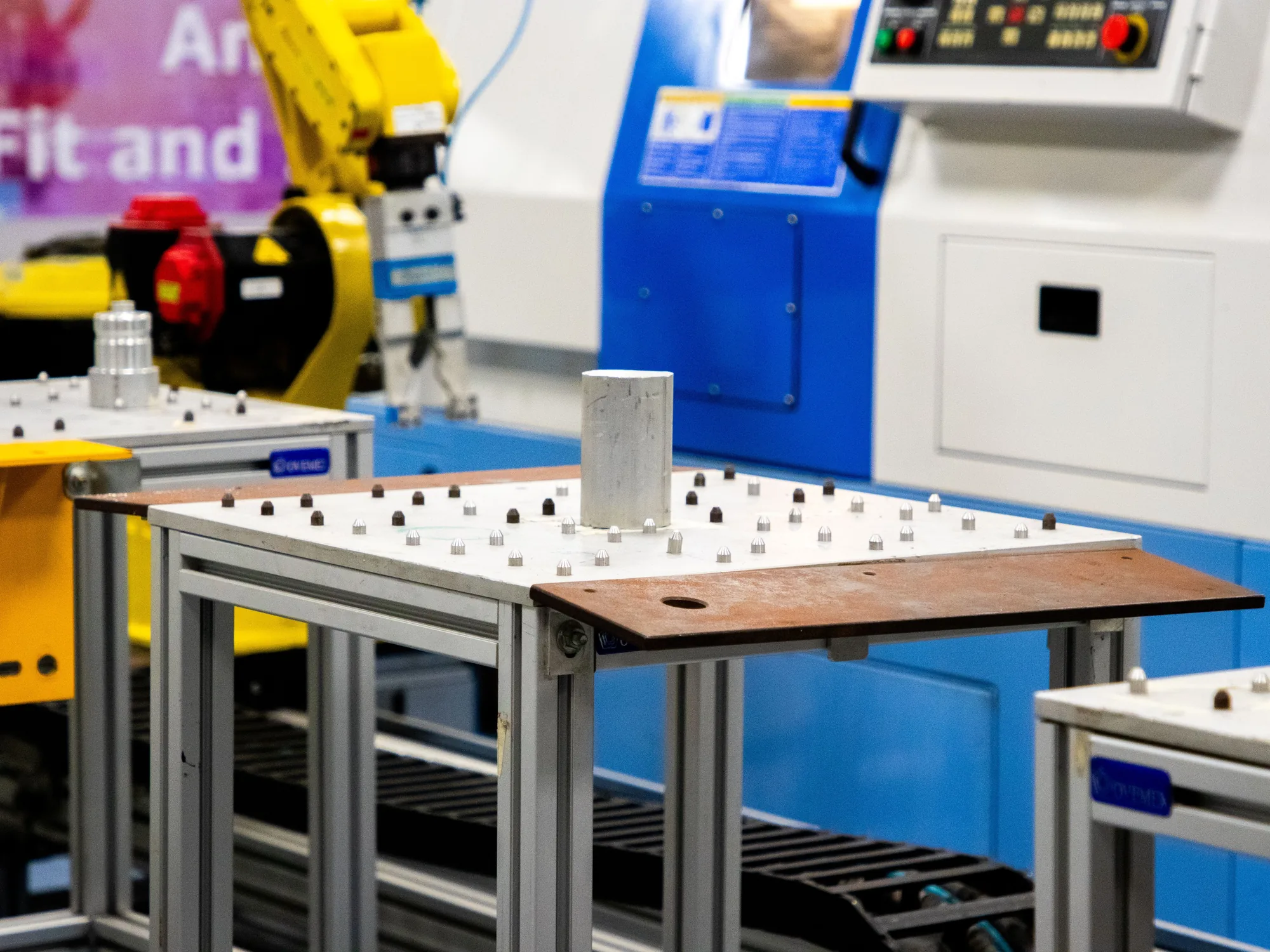
What a DFM review does
Design for manufacturing (DFM) is the drawing review that happens before a part is released to production. The goal is not to change the design for its own sake. It is to identify features that are difficult, expensive or ambiguous to machine, then give the buyer a clear choice before the price and lead time are locked.
Our review starts with the geometry, material, quantity, tolerance and finish. We check whether the selected process suits the part: CNC turning for round and concentric components, CNC milling for pockets and hole patterns, Swiss-type machining for small high-volume turned parts, and multi-axis work when several faces need features. The quote then reflects the actual route instead of a generic process assumption.
Send the right files
The most useful package is a STEP or IGES model plus a dimensioned PDF drawing. DWG, DXF or a clear dimensioned PDF can also start a quote. The drawing should include the part number, revision, material grade, quantity, units, general tolerance, critical dimensions, surface finish, thread standard and any checking or packing requirement.
If the model and drawing disagree, identify which document governs. If a part is based on an existing sample, include photographs and the dimensions that control fit. A sketch can start a discussion, but a controlled drawing is needed to confirm a production price and schedule. See the drawing and file requirements page for the document checklist.
Tolerances and datums
Apply tight tolerances only where the part function needs them. Bearing seats, bores, locating faces, hole positions and mating threads may need tighter control than outside edges, non-functional chamfers or clearance features. Our general tolerance is ISO 2768-m unless the drawing provides another general tolerance block; precision features can be held to +/-0.01 mm when the geometry and process support it.
Use a consistent datum structure so the important features can be measured from the same reference. A tolerance without a clear datum or measurement method can create a quotation question even when the nominal dimension is correct. If a feature needs a tighter value than +/-0.01 mm, identify it explicitly and ask for confirmation during the DFM review.
Geometry that increases machining cost
Deep pockets, deep narrow slots, thin walls, small internal radii and long unsupported features can require smaller tools, extra setups or slower cutting conditions. A standard internal corner radius is usually easier to machine than a sharp internal corner. A pocket that is slightly wider or shallower may reduce cycle time without changing the function.
Blind holes should show their required depth and the space needed for the drill point. Threads should identify the standard, size, pitch, depth and whether the hole is through or blind. Avoid specifying a thread deeper than the fastener engagement requires. For a bracket or housing, show which faces locate the mating part and which holes are clearance, tapped, reamed, counterbored or countersunk.
Material and finish choices
Material, quantity and finish should be considered together. Aluminium, stainless steel, steel, brass, copper and titanium have different cutting behavior and lead-time implications. A surface treatment can also change a thread, bore or press fit. State the finish, roughness, masking areas and any post-finish dimensional requirement on the drawing.
Finishing such as anodizing, passivation, black oxide, plating, polishing, brushing and heat treatment is handled through a vetted partner network under one quality process. The earlier the finish is included, the more accurately we can review the route, cost and schedule.
DFM checklist before requesting a quote
- Confirm the part number, drawing revision and units.
- Name the exact material grade and any hardness or condition.
- Mark critical dimensions, datums and functional tolerances.
- Specify threads, hole types, depths, chamfers and edge breaks.
- Identify surface finish, roughness and masking areas.
- State quantity, sample quantity, delivery target and required documents.
- Attach the model and drawing in the same revision.
We return DFM feedback and a quote within 24 hours after receiving the available drawing information. Samples typically ship in 5-10 days and production in 25-35 days after approval. For the full ordering sequence, see how to order custom machined parts or send your files through the request a quote form.
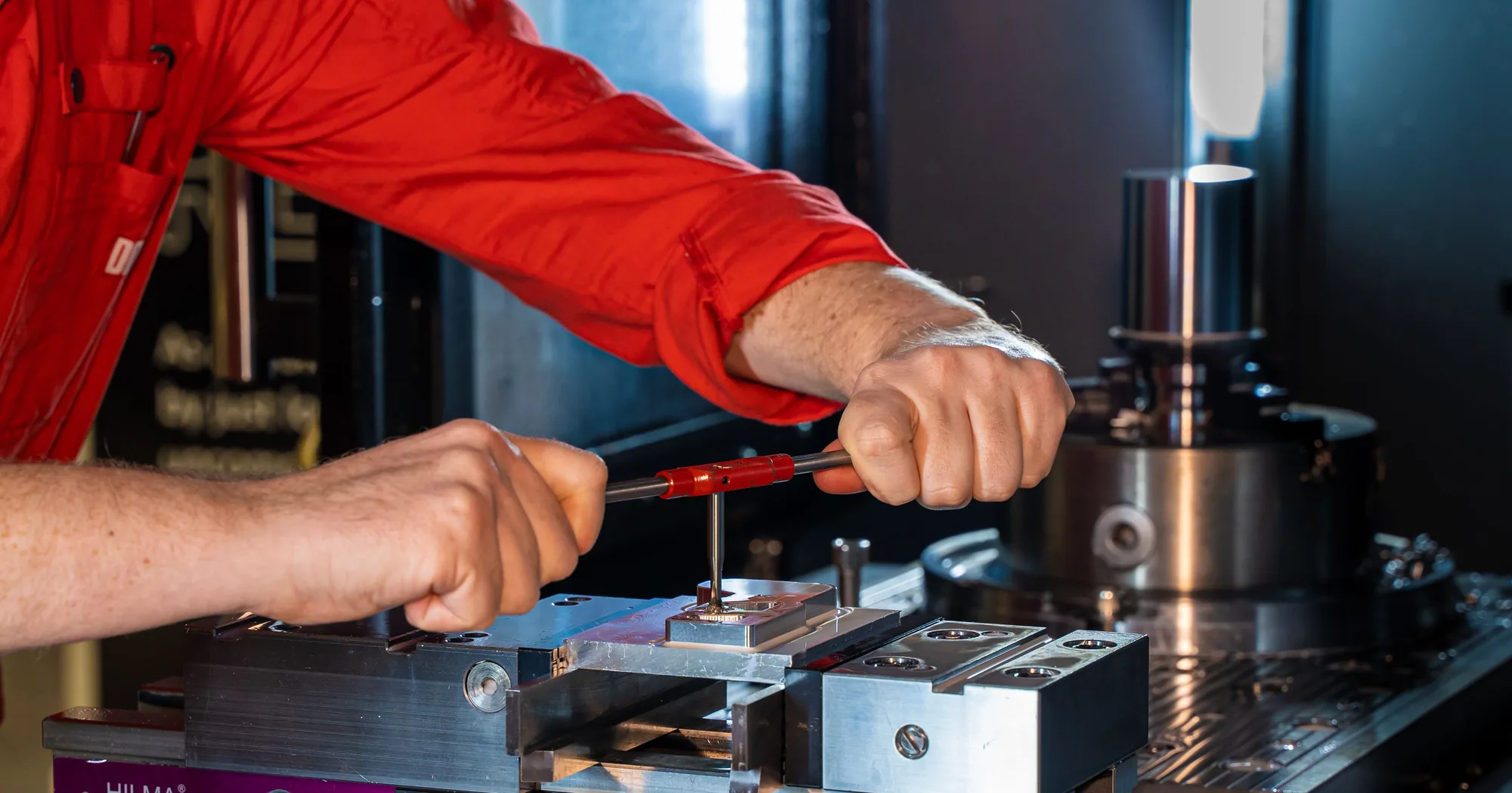
Send your drawing — quote in 24 hours
DFM feedback, material certificates and pre-shipment photos come with every order.